When Hips Collide #3
Drawings showing the secret line. I'm calling it a secret line, because it took me a month to find it. This secret line defines the lower claw angles on rotated hip rafters. This line is the "Intersection of the Hip Rafter Run Line & Hip Rafter Claw Line". Drawing a perpendicular from the DP Line defines the intersection point on the profile drawing of the rotated hip rafter. Drawing a line from the intersection of the plan view DP Lines to the intersection point draws the line representing the lower claw angle on the rotated hip rafter.
Drawing showing the plane that defines the lower claw angle on the rotated hip rafter.
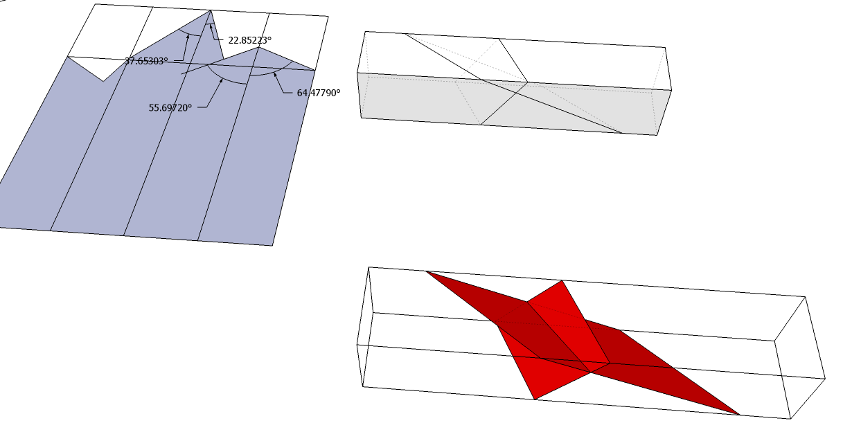
Drawing showing the hip rafter head cut unfolded. It also shows the 2 parallelogram planes that represent the head cut on the hip rafter. To layout the head cut on the timber you need 4 different angles and 1 dimension. The 2 upper claw angles that form one of the parallelogram cutting planes and the 2 lower claw angles of the rotated hip rafter that form the other parallelogram cutting plane. It's important to remember that the cutting planes are always parallelograms. Once you layout 2 of the angles of the parallelogram then the other 2 sides of the parallelogram are automatically developed by using the same 2 angles.
Drawing showing the geometry for the 2 upper claw angles and the 2 lower claw angles.
Drawing showing the intersection of the DP Lines.


Komentar
Posting Komentar